Banott Water Treatment Engineering Team | Published August 26, 2026
An EDI module removes dissolved ions from RO permeate continuously, without chemical regeneration, by combining ion-exchange resin with an applied electric field. Sizing the module correctly depends less on the EDI stack itself and more on feed water quality — the CO2, hardness, and conductivity limits set upstream by the RO system are what actually constrain what the EDI can handle.
EDI Module Selection: Feed Water Limits and RO Pairing
What an EDI Module Does
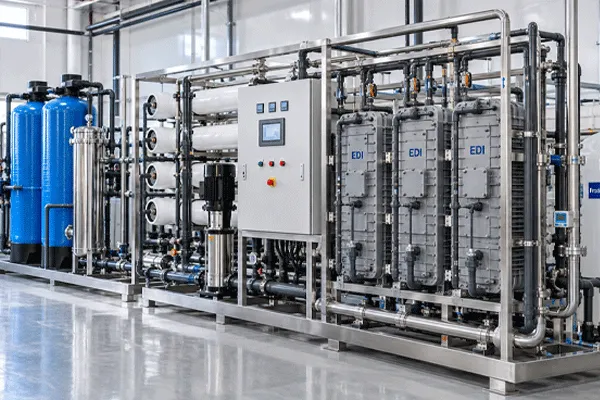
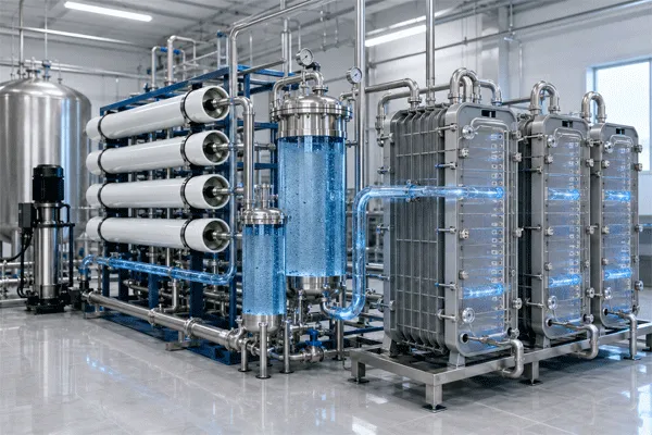
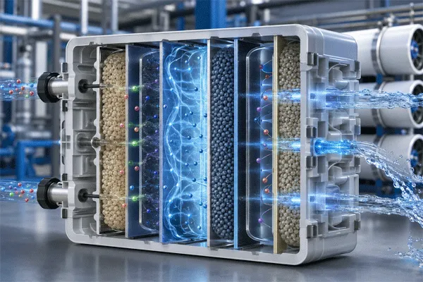
Electrodeionization (EDI) sits downstream of a reverse osmosis (RO) system and polishes RO permeate into high-purity water. Inside the module, ion-exchange resin captures dissolved cations and anions, while a DC electric field continuously drives those captured ions across ion-selective membranes into a concentrate stream — and, at the same time, regenerates the resin in place using water molecules split into H+ and OH- at the module’s electrodes. That in-place regeneration is the entire commercial case for EDI over conventional ion exchange: no acid or caustic regeneration chemicals, no resin replacement cycle, and no service interruption for regeneration downtime, provided the feed water stays within the module’s design window.
That last condition carries most of the weight. EDI is a polishing step, not a treatment step. It assumes RO has already removed the bulk of dissolved solids and organics. When feed quality drifts outside spec, the module doesn’t fail gracefully — resistivity drops, and depending on which limit was exceeded, either scaling risk or ion breakthrough follows.
Why Most EDI Problems Are RO Problems
Three feed water parameters cause the majority of EDI performance complaints, and all three are set by what the RO system does — or fails to do — before the water reaches the EDI stack.
Dissolved CO2 passes through RO membranes largely unaffected. RO rejection works on charged species and larger dissolved molecules; CO2 in its dissolved, un-ionized form crosses the membrane along with the water. Once that CO2 reaches the EDI module’s electric field, it ionizes into bicarbonate and carbonate ions. Those ions then consume exchange capacity and electrical current that would otherwise go toward removing the ions the system is actually meant to remove, which is why product water resistivity drops and power draw rises even when the RO system itself is operating normally. This is a common point of confusion: RO reduces TDS, but it does not reliably remove CO2, so a raw water source with high alkalinity can still deliver a CO2 load to the EDI stack that the RO train never touched.
Hardness that survives RO concentrates on the EDI’s concentrate side. Even a well-performing RO system passes some hardness through to permeate, and EDI further concentrates calcium and magnesium in its concentrate compartment as it removes them from the product stream. If influent hardness exceeds the module’s design limit, that concentration step precipitates as scale on the concentrate-side membranes and electrodes — a fouling mechanism specific to how EDI works, not a generic membrane fouling issue.
Feed conductivity above the design window overwhelms the module’s removal capacity. This usually traces back to an RO membrane integrity issue, a blend valve set incorrectly, or a startup sequence that feeds EDI before the RO permeate has stabilized. The EDI stack has a rated ionic load it can handle continuously; feed above that load produces permeate that never reaches spec, regardless of how well the module itself is built.
Typical Feed Water Limits That Constrain EDI Sizing
The table below reflects the parameters that generally govern EDI feed water acceptability across the industry. Exact thresholds vary by module design, resin configuration, and manufacturer, so treat these as the categories to check during design, not as Banott’s own guaranteed limits — see the parameter section below for what Banott has and has not published.
| Feed Parameter |
Why It Matters for EDI |
Typical Consequence If Exceeded |
| Feed conductivity / TDS |
Sets the ionic load the module must remove per pass |
Product resistivity fails to reach target; possible breakthrough |
| Total hardness (as CaCO3) |
Concentrates on the electrode/concentrate side during operation |
Scaling, reduced flow, increased cleaning frequency |
| Free chlorine / oxidants |
Degrades ion-exchange resin and membranes |
Permanent capacity loss, shortened module life |
| Dissolved CO2 / alkalinity |
Ionizes inside the module, adding unwanted ionic load |
Reduced resistivity, higher current draw, lower efficiency |
| Silica |
Can scale on concentrate side at high recovery |
Flow restriction, cleaning frequency increase |
| TOC |
Fouls resin and membranes over time |
Gradual capacity decline |
EDI Module Selection: Feed Water Limits and RO Pairing
The Recovery-Rate and Sizing Trade-Off
Module sizing is not simply “flow rate in, module out.” Two feed parameters interact directly with how the EDI train is sized and configured for continuous operation:
- Confirm the RO permeate quality the EDI will actually see — not the RO’s nameplate rejection rate, but the real, monitored conductivity and hardness at the point EDI takes feed, including any blend or bypass streams.
- Check dissolved CO2 and total alkalinity in the raw water source; if alkalinity is high, a decarbonator or forced-draft degasifier ahead of EDI is usually more cost-effective than oversizing the EDI stack to absorb the CO2 load.
- Set target recovery rate against the hardness limit, not against a generic industry number — a higher recovery rate concentrates hardness further on the reject side and narrows the acceptable feed hardness window.
- Confirm minimum continuous flow requirements with the module design. Unlike batch resin systems, EDI stacks generally need a sustained minimum flow to keep the electrochemical process stable; intermittent or low-flow operation is a common startup misconfiguration.
- Build in feed monitoring — conductivity and, where alkalinity is a known risk, CO2 — ahead of the EDI inlet, so an RO upset is caught before it reaches the EDI stack rather than after resistivity has already dropped.
A common misconception worth flagging directly: assuming that because RO handles “desalination,” it also handles CO2 removal, and therefore no separate decarbonation step is needed. CO2 removal is a function of RO membrane rejection characteristics for uncharged dissolved gases, which is fundamentally different from ionic rejection — the two should not be assumed to track together at the design stage.
EDI Compared With Conventional Ion Exchange
Compared with conventional two-bed or mixed-bed ion exchange polishing, EDI’s main advantage is continuous operation without acid/caustic regeneration chemicals or the associated downtime and neutralization waste stream. The trade-off runs the other way on feed water tolerance: conventional ion exchange resin is more forgiving of hardness and conductivity excursions because it is simply exhausted and regenerated on a schedule, while an EDI stack operating outside its feed water window degrades in resistivity and, over time, in resin and membrane life. The choice between the two is usually a question of whether the site can guarantee stable RO permeate quality upstream, not a straightforward “EDI is newer, therefore better” decision.
EDI Module Selection: Feed Water Limits and RO Pairing
Banott EDI Module Parameters
Banott’s EDI modules are positioned for continuous ion removal downstream of RO, integrated into pure water treatment trains without chemical regeneration. The following parameters are confirmed from Banott’s published material:
- Process function: continuous electrodeionization downstream of RO, removing residual ions without chemical regeneration
- Typical placement: integrated after RO to raise product water purity and simplify operation for continuous production
The following parameters are not published and available on enquiry: module model designations, rated capacity (m³/h), guaranteed product water resistivity (MΩ·cm), feed water acceptance limits (conductivity, hardness, CO2, TOC), recovery rate, and power consumption. A design institute specifying Banott EDI modules into a project should request this datasheet directly before finalizing a sizing calculation — the feed water limits discussed above are the categories to ask for, not values to assume.
Pricing for EDI modules is not published; Banott’s site indicates industrial RO membranes are offered in standard 4040 and 8040 formats without listed pricing, and EDI modules follow the same request-a-quote model.
FAQ
Q: Can EDI replace RO entirely?
A: No. EDI is designed to polish RO permeate, not to treat raw or lightly pretreated water. Feeding EDI directly with high-TDS source water exceeds its design ionic load and is not how the technology is intended to operate.
Q: Does EDI need any chemicals at all?
A: EDI does not require acid or caustic regeneration chemicals for the resin, which is its main operating advantage over conventional ion exchange. Pretreatment steps such as antiscalant dosing on the RO side, or occasional cleaning-in-place for the EDI stack itself, are separate from resin regeneration and may still apply.
Q: What happens if RO permeate hardness spikes temporarily?
A: Depending on how far above the design limit and for how long, the result ranges from reduced resistivity to scale formation on the concentrate side that requires a cleaning cycle to reverse. Continuous feed monitoring ahead of the EDI inlet is the standard way to catch this before it becomes a scaling event.
Q: Is EDI capacity fixed once the module is installed, or can it be sized for future expansion?
A: EDI trains are typically configured in parallel stacks, so capacity can be planned with spare stack positions or modular expansion in mind at the design stage — this is a system configuration question to raise with the supplier during specification, not something to assume is available after installation.











 13:47
13:47