Инженерная команда компании «Banott Water Treatment» — Опубликовано 28 августа 2026 года
Определение размеров подводного MBR с полыми волокнами Расчет заключается в преобразовании расчетного расхода в требуемую площадь мембран, а затем в делении этой площади на площадь одного модуля. Модули с полыми волокнами компании Banott имеют площадь 3 м² (MBRIII3C), 10 м² (MBRIII10C) и 20 м² (MBI120C); данные о расчетном расходе, диапазоне перепада давления (TMP) и условиях CIP пока не опубликованы и должны запрашиваться напрямую.
Погружные мембранные модули MBR: технические характеристики и расчет размеров
Что означает термин “погруженный” в данном расчете
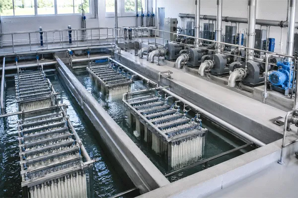
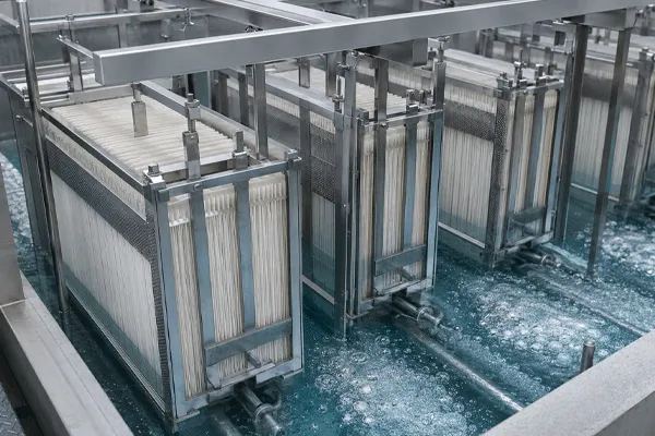
При погружной конфигурации мембранный модуль размещается непосредственно в резервуаре для смешанной жидкости, при этом пермеат проходит через стенку волокна под действием вакуума, а не перекачивается через поверхность мембраны под давлением. Это различие имеет значение при расчете параметров установки, поскольку движущая сила ограничена — типичные погружные системы работают значительно ниже предельных значений перепадного давления (TMP), используемых в ультрафильтрации под давлением, что отчасти объясняет, почему при расчете параметров установки вопросам контроля загрязнения и проектированию аэрации уделяется больше внимания, чем в случае установки под давлением.
Эта статья не является определительной, поэтому в дальнейшем в тексте предполагается, что читатель уже знает, что MBR и сразу переходит к расчетам количества модулей.
Основная формула: соотношение потока к количеству модулей
Количество модулей, необходимых для поезда, определяется тремя числами:
- Расчетный расход (Q) — пиковый или среднесуточный расход, который должна обрабатывать установка, в м³/сутки. Этот показатель определяется на основе данных о поступающих стоках по проекту, а не по каталогу мембран.
- Проектный расход (J) — устойчивая скорость проникновения на единицу площади мембраны, выраженная в ЛМЧ (литрах на квадратный метр в час). Это величина, позволяющая пересчитать расход в площадь.
- Эффективная площадь мембраны на модуль (A) — определяется выбранной моделью.
Зависимость выглядит следующим образом:
Требуемая общая площадь мембран (м²) = Расчетный расход (м³/сутки) ÷ [Расчетный поток (л/м²·ч) × 24 ÷ 1 000]
Количество модулей = Общая требуемая площадь мембран ÷ Эффективная площадь одного модуля
Расчетный расход — это термин, который в данном уравнении в наибольшей степени отражает инженерную оценку, поскольку он должен учитывать соотношение пикового и среднего расходов, температуру, концентрацию взвешенных веществ в смешанной жидкости, а также запас по заиливанию, который проектировщик хочет оставить в резерве. Кроме того, это параметр, который Банотт пока не опубликовал для MBR с полыми волокнами строка — прежде чем применять эту формулу к реальному проекту, обратите внимание на отмеченный пробел ниже.
Подтвержденные технические характеристики модуля
| Модель |
Эффективная площадь мембраны |
Настройка |
Расчетный поток |
Серия TMP |
Скорость аэрации/промывки |
Размеры модуля |
Протокол CIP |
| MBRIII3C |
3 м² |
Погруженное полое волокно |
Не опубликовано — предоставляется по запросу |
Не опубликовано — предоставляется по запросу |
Не опубликовано — предоставляется по запросу |
Не опубликовано — предоставляется по запросу |
Не опубликовано — предоставляется по запросу |
| MBRIII10C |
10 м² |
Погруженное полое волокно |
Не опубликовано — предоставляется по запросу |
Не опубликовано — предоставляется по запросу |
Не опубликовано — предоставляется по запросу |
Не опубликовано — предоставляется по запросу |
Не опубликовано — предоставляется по запросу |
| MBI120C |
20 м² |
Погруженное в жидкость полое волокно — классификация ожидает подтверждения |
Не опубликовано — предоставляется по запросу |
Не опубликовано — предоставляется по запросу |
Не опубликовано — предоставляется по запросу |
Не опубликовано — предоставляется по запросу |
Не опубликовано — предоставляется по запросу |
Схема наименования модели MBI120C напоминает серию плоских листов компании Banott, хотя в библиотеке ресурсов она указана в разделе «полые волокна»; этот вопрос пока не согласован с командой по продукту, поэтому до получения подтверждения указывайте её с этой оговоркой.
Погружные мембранные модули MBR: технические характеристики и расчет размеров
Почему поле «Количество модулей» пока нельзя заполнить
Если эффективная площадь подтверждена, а расчетный поток не подтвержден, то во второй части приведенной выше формулы отсутствует правая часть, которую нужно вычислить. Пример с подставкой предположительного значения потока будет выглядеть полным на бумаге, но окажется неверным в тендерной заявке — именно такой вариант ошибки больше всего беспокоит экспертов из проектного института. Вместо того чтобы оценивать правдоподобное значение LMH, в данной статье ограничиваются формулой и подтвержденными данными по площади, а значение потока рассматривается как элемент, требующий дополнительных данных.
После того как расчетный расход, диапазон TMP и интенсивность аэрации определены, приведенный здесь пример расчета не представляет сложности: выберите расчетный расход, разделите его на расход, чтобы получить площадь, разделите на площадь модуля, чтобы получить количество модулей, затем округлите в большую сторону до ближайшего целого числа модулей и добавьте резервные агрегаты в соответствии с принципами резервирования.
Распространенное заблуждение: площадь, указанная на заводской табличке, не является расчетной основой
Распространенной ошибкой при расчете мощности является использование номинального максимального потока модуля в качестве расчетного потока для всей технологической линии. Номинальный максимальный поток — это краткосрочный показатель, рассчитанный для чистой воды; непрерывная эксплуатация погружного MBR с такой интенсивностью при обработке реальной смешанной жидкости ускоряет загрязнение и сокращает интервал между химическими очистками. Расчетный расход, используемый при определении количества модулей, должен быть ниже номинального максимального значения, а запас по расчету должен рассчитываться с учетом склонности конкретных сточных вод к загрязнению — что является еще одной причиной, по которой этот показатель должен быть рассчитан инженерной командой Banott на основе фактических данных о поступающих стоках, а не взяты из общего каталога.
Предварительные условия для просеивания и аэрации
Количество модулей позволяет ответить лишь частично на вопрос о выборе размера системы. Прежде чем количество погруженных в воду модулей с полыми волокнами станет значимым показателем, должны быть выполнены два предварительных условия:
- Тонкая очистка перед мембранным резервуаром. Модули с полыми волокнами подвержены разрыву волокон и засорению волокнистыми или нитевидными твердыми частицами, которые не задерживаются грубой решетчатой сеткой. Тонкое просеивание (обычно в диапазоне 1–3 мм по всей отрасли, это не показатель, характерный только для Banott) является стандартной практикой перед погруженными в воду цепочками полых волокон.
- Непрерывная аэрация крупными пузырьками в мембранном резервуаре. Промывочный воздух предотвращает осаждение твердых частиц на поверхности волокон между циклами пропускания пермеата. Компания Banott не публиковала конкретные значения расхода промывочного воздуха для своей серии полых волокон, поэтому этот показатель, наряду с потоком и перепадным давлением (TMP), остается предметом запроса данных.
Пропуск любого из этих предварительных условий является распространенной причиной того, что поезд, в котором количество модулей рассчитано правильно, после ввода в эксплуатацию всё равно демонстрирует низкую производительность.
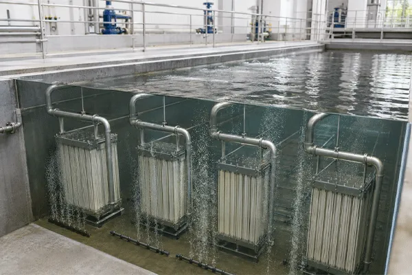
Погружные мембранные модули MBR: технические характеристики и расчет размеров
Как это соотносится с традиционной модернизацией системы с активным илом
По сравнению с установкой системы фильтрации ниже по потоку от традиционной технологии с активным илом, погруженная Модуль MBR При расчете размеров мембранного биологического реактора (MBR) этап осветления интегрируется непосредственно в биологический резервуар, а не реализуется в виде отдельной стадии доочистки. Это позволяет объединить два проектных решения — расчет размеров вторичного осветлителя и доочистку стоков — в один расчет площади мембран, что является одной из причин, по которой модернизация с использованием технологии MBR может быть реализована в пределах существующей площади резервуара, в то время как модернизация с установкой традиционного вторичного осветлителя оказалась бы невозможной.
ЧАСТО ЗАДАВАЕМЫЕ ВОПРОСЫ
Вопрос: Можно ли рассчитать размеры погруженной в воду цепочки MBR, используя только данные об эффективной площади мембран, опубликованные здесь?
A: Нет. Сама по себе площадь определяет лишь знаменатель. Для расчёта необходимой общей площади в первую очередь требуется расчётный поток — который для данной линейки продукции пока не опубликован.
Вопрос: Является ли MBI120C модулем с полыми волокнами или плоским листом?
Ответ: В библиотеке ресурсов Banott данная модель в настоящее время указана в разделе «MBR с полыми волокнами» с эффективной площадью 20 м², однако схема наименования модели соответствует серии плоских листов. Этот вопрос пока не согласован с командой по продукту, поэтому перед указанием модели в тендерной документации необходимо получить подтверждение.
Вопрос: Какой резерв следует добавить к рассчитанному количеству модулей?
A: Подход к резервированию (модуль N+1, резервный поезд или отсутствие резерва) представляет собой проектное решение, принимаемое совместно с инженерной командой Banott с учетом степени критичности установки и возможностей доступа для технического обслуживания, а не фиксированное правило, которое можно обобщенно сформулировать в данной статье.
Вопрос: Публикует ли компания Banott цену за модуль?
A: Информация о цене за каждый модуль не публикуется; для уточнения цены необходимо обратиться напрямую.











 14:46
14:46