Banott Engineering Team | Membrane Process & System Engineering, Qingdao Banott Environmental Technology Co., Ltd. | Published: August 21, 2026
MBR wastewater treatment combines activated sludge with membrane filtration in place of a secondary clarifier. The membrane retains all biomass, so the tank runs at higher MLSS in a smaller footprint and produces effluent low in TSS. The trade is aeration energy, cleaning labor, and membrane replacement cost.
Tratamento de águas residuais por MBR: como funciona e quando é adequado
What an MBR actually replaces
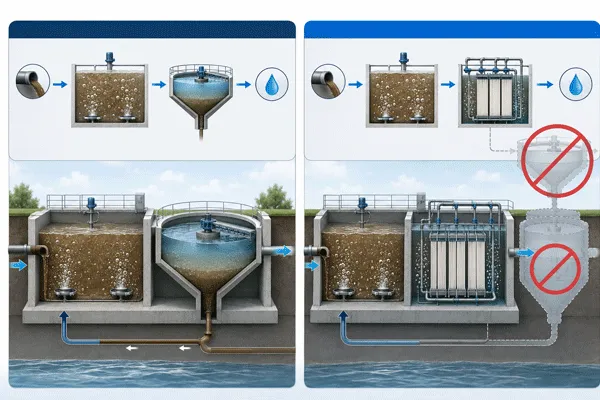
A conventional biological plant separates treated water from sludge by gravity. Sludge settles in a clarifier, clear water flows over the weir, and settled sludge is returned to the aeration tank. That separation step is the constraint on the whole plant: the clarifier has to be large, the sludge has to settle well, and when it does not settle well — filamentous bulking, a temperature swing, a shock load — solids leave with the effluent and the discharge limit is missed.
An MBR removes the clarifier and pulls water through a membrane instead. Separation stops depending on how the sludge behaves and starts depending on pore size. Biomass cannot escape, regardless of its settling characteristics.
Everything else that people say about MBR follows from that one substitution:
- Because biomass cannot escape, the tank can be operated at a much higher solids concentration, which is why the biological volume shrinks.
- Because separation is physical, effluent TSS is consistently low and turbidity is stable through upsets that would break a clarifier.
- Because sludge age can be extended, slow-growing organisms such as nitrifiers stay in the system, which supports ammonia removal at lower temperatures.
- Because there is no clarifier, the plant footprint drops sharply, and an existing tank can often be converted rather than extended.
- Because the membrane is now the separation barrier, it fouls, and keeping it clean becomes a permanent operating task rather than an occasional one.
That last point is where most vendor material goes quiet, and it is the one an operating manager should read first.
Inside the tank: how the separation works
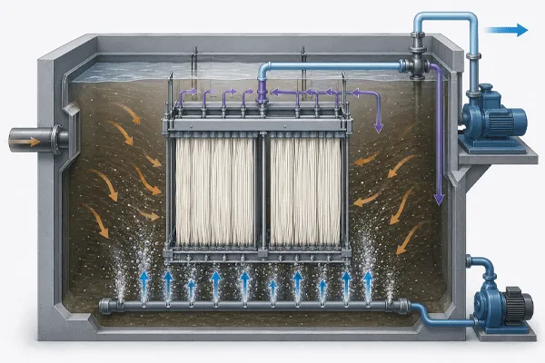
In a submerged MBR the membrane modules sit directly in the aeration tank or in a dedicated membrane tank fed from it. A permeate pump draws water through the membrane from the outside in, leaving biomass, suspended solids and most colloids behind. The driving force is a small negative pressure on the permeate side, measured as transmembrane pressure.
Air is blown along the membrane surface continuously. This scour air is not there to supply oxygen to the biology, although some of it does; its job is to keep a cake layer from consolidating on the membrane surface. Scour air is a separate blower duty from process aeration, and it is the single largest reason MBR energy consumption sits above a conventional plant.
Periodically the permeate pump reverses briefly, pushing filtered water back through the membrane to lift the fouling layer. This relaxation and backwash cycle handles reversible fouling. What it does not handle accumulates, TMP climbs, and at some threshold the modules are chemically cleaned.
Two cleaning regimes exist in parallel on most plants:
- Maintenance cleaning, a short in-place dose of hypochlorite or acid at low concentration, performed frequently, often weekly or fortnightly, without removing modules.
- Recovery cleaning, a longer soak at higher concentration, performed when maintenance cleaning no longer restores flux, typically a small number of times per year.
- Physical removal and inspection, needed when hair, fiber or grease has bridged between membranes and chemistry alone will not clear it.
The frequency of each is set by the influent, not by the membrane brand. Any supplier quoting a cleaning interval without asking about your feed is quoting a number from another plant.
The footprint argument, stated honestly
Footprint is the reason most managers look at MBR at all, and the gain is real. Removing the clarifier and running at elevated MLSS reduces the biological reactor volume required for the same load.
Conventional activated sludge plants are commonly designed around a mixed liquor concentration in the low thousands of mg/L, because the clarifier sets an upper bound on what can be settled. MBR designs routinely operate several times higher, because nothing needs to settle. Ask your process designer to state the MLSS the design assumes, because that assumption drives both the tank volume you save and the aeration energy you spend. A design at the upper end of the range gains you the most floor space and costs you the most oxygen transfer efficiency, since thicker mixed liquor transfers oxygen less readily. The two effects are linked, and a proposal that claims the footprint benefit without acknowledging the aeration penalty has not been fully costed.
There is a second footprint effect that gets less attention and is often more valuable in a retrofit. Because the process no longer needs a clarifier, an existing aeration tank can sometimes absorb a capacity increase in place, inside the existing plot boundary and the existing concrete. For a plant boxed in by a fence line, that is often the entire business case.
What it costs to run, line by line
| Cost line |
How it behaves in an MBR |
What to ask for in a quotation |
| Process aeration |
Higher than conventional per unit of load, because oxygen transfer efficiency falls as MLSS rises |
The alpha factor assumed, at the design MLSS, not a generic value |
| Membrane scour air |
An additional, continuous blower duty with no conventional equivalent |
Scour air rate, whether it is continuous or cyclic, and the connected kW |
| Permeate pumping |
Small compared with aeration, but continuous |
Design TMP and the TMP at which the plant is considered to need cleaning |
| Produtos químicos de limpeza |
Ongoing hypochlorite and acid consumption, plus the labor around each cleaning |
Assumed maintenance cleaning frequency and dose, and the same for recovery cleaning |
| Substituição da membrana |
A capital line that recurs, unlike a clarifier |
Stated membrane life, the cleaning regime it assumes, and the module price basis for replacement years later |
| Sludge handling |
Lower sludge production at extended sludge age, but the sludge is often harder to dewater |
Waste sludge quantity and the dewatering assumption behind it |
| Screening |
Fine screening is mandatory, not optional, and it has its own maintenance |
Screen aperture required by the membrane supplier, and who is responsible if it is undersized |
Compared with conventional clarifier-based plants, which concentrate cost in civil works and land, MBR shifts spending toward energy, chemicals and periodic module replacement. Compared with fixed-film approaches in the same category, which carry a lighter cleaning burden, MBR buys effluent consistency and footprint at the price of that ongoing membrane management. Neither trade is inherently better; they suit different plants, and the deciding factor is usually whether the site has space and whether it has operators.
Five situations where MBR is the wrong call
This is the section most product pages leave out. If any of the following describe your plant, an MBR should be argued for carefully rather than assumed.
Your influent carries fats, oils and grease that are not removed upstream. Free oil and grease coat membrane surfaces and are not lifted by scour air or backwash. Chemical cleaning restores some flux and then it declines again faster. The fix is upstream separation, and if that upstream stage is not in the project scope and budget, the MBR will not perform as quoted.
Your flow is intermittent or highly seasonal. Membranes need to stay wet and the biology needs a steady food supply. A plant that runs one shift a day, or five months a year, imposes standby, preservation and restart requirements that add operating complexity. It can be engineered, but the complexity should be priced before selection, not discovered afterward.
Your discharge limit does not require it. If the permit is met by a well-run conventional plant with room to expand, an MBR adds operating cost for effluent quality nobody is asking for. The case changes if reuse is planned, because MBR permeate is a reasonable feed to an RO stage where conventional secondary effluent is not.
You do not have operator coverage for the cleaning regime. Maintenance cleaning is a scheduled task with chemical handling and a defined procedure. Plants that miss it for a few months arrive at a TMP the membranes do not fully recover from. If the site has one utilities technician covering multiple systems, be honest about that during selection rather than after.
The influent contains substances that attack the membrane or the biology. Solvents, high concentrations of oxidants, abrasive grit, or a toxic slug that kills the biomass. The membrane survives some of these and not others, and the biology is often the more fragile of the two. Characterize the worst case in the influent, not the average.
A sixth case sits at the boundary. Very high strength organic águas residuais can be treated biologically, but the oxygen demand may make aeration the dominant cost regardless of separation method. In those streams the real question is whether anaerobic pretreatment belongs upstream, and MBR selection should wait until that is settled.
Tratamento de águas residuais por MBR: como funciona e quando é adequado
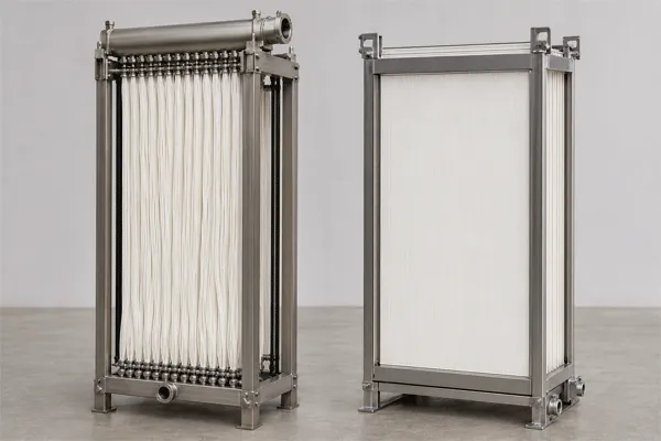
Hollow fiber or flat sheet: what the choice changes
Both configurations do the same job. The differences that reach an operating manager are cleaning behavior and packing density.
| Dimensão |
Fibra oca |
Chapa plana |
| Densidade de enchimento |
Higher membrane area per tank volume, so a smaller membrane tank for the same flux |
Lower area per volume, so more tank space for the same duty |
| Behavior with hair and fiber |
More susceptible to bridging between fibers; fine screening specification is stricter |
The gap between plates is more tolerant of fibrous material |
| Physical cleaning |
Fibers can be damaged by rough handling during inspection |
Plates can be cleaned by hand between panels |
| Sludging within the module |
Requires attention to scour distribution across the bundle |
Channels between plates are more visible and easier to check |
| Module handling |
Lighter per unit area, easier to lift |
Heavier assemblies, but individual sheets can be replaced |
| Corte típico |
Larger flows where footprint governs |
Smaller and mid-size plants, and difficult influents where cleaning access matters |
For a plant with strong screening and a stable feed, the higher packing density of hollow fiber usually wins. For a difficult influent, a small operating team, or a site where modules will realistically be cleaned by hand, flat sheet reduces the operational risk even though it uses more tank volume.
Banott MBR modules: published parameters
| Produto |
Configuração |
Área efectiva da membrana |
Material and flow |
| MBRIII3C |
Hollow fiber, submerged |
3 m² |
Não publicado |
| MBRIII10C |
Hollow fiber, submerged |
10 m² |
Não publicado |
| MBI120C |
Hollow fiber, submerged |
20 m² |
Não publicado |
| Compact Flat Sheet MBR Module |
Flat sheet, submerged |
Não publicado |
PVDF membrane with PET linen support, outside-in flow |
| Integrated Flat Sheet MBR Module |
Flat sheet, integrated module structure |
Não publicado |
PVDF membrane with PET linen support, outside-in flow |
| Flat Sheet MBR Module |
Flat sheet, standard configuration |
Não publicado |
PVDF membrane with PET linen support, outside-in flow |
Pore size, design flux, operating TMP range, scour air rate, module dimensions, CIP protocol and expected membrane life are not published for either series and are provided against a stated influent analysis on enquiry. Pricing is quotation-based; no list price is published for MBR modules.
Banott’s stated design approach starts from the customer’s influent data and the required effluent standard rather than a catalog model number, and the company describes its water treatment engineering team as holding close to two decades of experience in membrane separation technology and engineering application. For a manager at the shortlisting stage, the practical use of that is simple: send the influent analysis and the discharge limit, and ask for the aeration and cleaning assumptions in writing alongside the module selection.
Tratamento de águas residuais por MBR: como funciona e quando é adequado
Before you shortlist: seven things to have on paper
- Influent analysis covering the worst case, not the average — COD, BOD, TSS, ammonia, total nitrogen, phosphorus, FOG, temperature range, pH range, and any known toxic or solvent load.
- The discharge limit you must meet, and whether reuse is planned now or within the asset life.
- Available footprint, stated as the actual plot or tank you can use, including access for module removal.
- Existing assets you intend to keep, particularly tank volumes, blowers and screening.
- Operator coverage: how many people, how many hours, and what other systems they carry.
- Current sludge disposal cost per tonne and the dewatering equipment you already own.
- Energy tariff, including any demand charges, since a continuous scour blower affects load profile as well as consumption.
- The years over which the plant will be evaluated financially, because membrane replacement lands inside a ten-year window and outside a five-year one.
Suppliers who receive all of this return proposals you can compare. Suppliers who receive only a flow rate return proposals that differ mainly in how optimistic their assumptions were.
FAQ
Q: Does an MBR really use more energy than a conventional plant?
A: Generally yes, and the gap comes from two places: continuous membrane scour air, which has no conventional equivalent, and reduced oxygen transfer efficiency at higher mixed liquor concentrations. The size of the gap depends on the design MLSS and the scour strategy, which is why both should be stated in the quotation rather than discussed in general terms.
Q: How long do MBR membranes last?
A: Any figure quoted without a cleaning regime attached is not usable. Membrane life depends on cleaning frequency, chemical concentration, influent character and how consistently the maintenance schedule is followed. Ask for the life figure together with the regime it assumes, and treat the regime as part of the warranty terms.
Q: Can I convert my existing activated sludge plant to MBR?
A: Often, and the conversion is one of the stronger cases for MBR because it uses existing concrete. What has to be added is fine screening, membrane tank arrangement, scour blowers, permeate and backwash equipment, and a cleaning system. What has to be checked is whether existing blower capacity and tank geometry suit the new duty.
Q: Is MBR effluent good enough for reuse?
A: It is a reasonable feed for a reuse train, and low, stable TSS is the reason. Whether it is directly reusable depends on what you need to remove. Dissolved salts pass through an MBR, so reuse duties with a conductivity requirement need an RO stage downstream, with the MBR acting as pretreatment.
Q: What screening does an MBR need?
A: Finer than a conventional plant, and the requirement comes from the membrane supplier rather than from general practice. Hollow fiber configurations are usually stricter than flat sheet. Undersized screening is one of the most common causes of early membrane trouble, and it is cheaper to correct at design stage than during operation.
Q: What MBR specifications does Banott publish?
A: Effective membrane area for the hollow fiber modules at 3, 10 and 20 m², and PVDF with PET linen support in outside-in flow mode for the flat sheet modules. Pore size, design flux, TMP range, scour air rate, dimensions and CIP protocol are provided on enquiry against a stated influent analysis.











 10:22
10:22