Banott Engineering Team | Membrane Process & System Engineering, Qingdao Banott Environmental Technology Co., Ltd. | Published: August 20, 2026
For UF ahead of RO, material and flow mode are separate decisions. PVDF suits feeds with sustained oxidant exposure and aggressive backwash; PES suits high-temperature cleaning and tighter, sharper cut-offs. Inside-out favors low-solids feeds; outside-in tolerates fibers and higher TSS. The two choices interact, so decide them together.
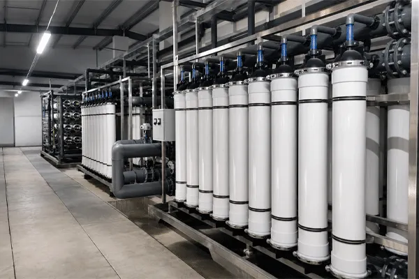
Membrana UF a fibra cava: PVDF vs PES e modalità di flusso
Two decisions get collapsed into one, and that is where specifications go wrong
Most UF module catalogues present the polymer and the flow configuration as a single product line: you pick a model number and both come bundled. For a design institute writing an equipment specification, that bundling hides the actual engineering question, because the polymer answers a chemistry problem and the flow mode answers a hydraulics problem, and the same feed water can push those two answers in different directions.
A high-turbidity surface water with seasonal algae and a chlorinated raw main is one such case. The chlorine argues one way on material; the solids and filamentous matter argue another way on configuration. If the specification treats them as one choice, one of the two constraints gets quietly dropped.
The rest of this article separates them, then puts them back together against four feed cases.
PVDF vs PES: the properties that change a design
Both polymers are used across the UF range, and both are supplied in modified or blended forms rather than as pure base resin. The differences that survive into a plant specification are chemical tolerance, mechanical behavior under backwash, and thermal limits during cleaning.
| Dimension |
PVDF (polyvinylidene fluoride) |
PES (polyethersulfone) |
| Base hydrophilicity |
Hydrophobic base polymer; hydrophilicity comes from blending or surface modification, so performance depends on the manufacturer’s modification method, not on the polymer name |
More hydrophilic than unmodified PVDF, which usually shows as lower initial fouling on organic-bearing feeds |
| Oxidant tolerance |
Generally specified for higher sustained free chlorine exposure; the deciding number is the cumulative ppm-hour rating, not the peak ppm |
Tolerates chlorine for cleaning, but sustained exposure limits are typically stated lower; check whether the rating covers continuous or intermittent dosing |
| Alkali tolerance |
Attacked by strong caustic at elevated concentration and temperature; confirm the upper pH limit at CIP temperature, not at 25 °C |
Wider tolerance to caustic cleaning, which matters when organic fouling drives the CIP recipe |
| Solvent tolerance |
Dissolved by polar aprotic solvents (DMF, NMP, DMAc) used in its own casting process |
Sensitive to aromatic hydrocarbons and some ketones |
| Mechanical behavior |
More flexible and elongation-tolerant, which supports vigorous air scour and frequent backwash cycles |
More rigid; fiber breakage risk rises with aggressive mechanical cleaning if the module is not designed for it |
| Thermal limit |
Confirm module-level limit, which is normally set by the potting resin rather than the fiber |
Higher polymer thermal stability, useful where hot CIP or hot water sanitization is part of the operating plan |
| Where it fails a spec review |
Caustic-heavy CIP recipes at temperature |
Continuous oxidant dosing in the feed |
Two points deserve emphasis because they are the ones that get argued about during tender clarification.
First, the potting and housing usually fail before the fiber does. A PES fiber rated to a high temperature installed in a module potted with a resin rated lower gives a module limit set by the resin. Specify the limit at module level and require the supplier to state which component sets it.
Second, “chlorine resistant” without a ppm-hour figure is not a specification. Ask for the exposure basis: concentration, contact pattern, temperature, and the flux or bubble-point retention criterion used to define end of life. Two suppliers can both write “chlorine resistant” and mean tolerances that differ by an order of magnitude.
When the material choice is already made for you
The polymer is effectively fixed, not chosen, in these situations:
- The feed carries continuous free chlorine or chloramine that cannot be removed upstream. Material has to match sustained oxidant exposure.
- The plant standardizes CIP on hot caustic because the fouling is proteinaceous or otherwise organic-dominated.
- The module has to survive daily air scour at design intensity for a decade, and the operator will not moderate it.
- A solvent trace exists in the feed. Then the question stops being PVDF versus PES and becomes whether polymeric UF is appropriate at all.
- An existing plant is being retrofitted and the replacement module must match the installed rack geometry, which limits available materials to whatever the compatible module range offers.
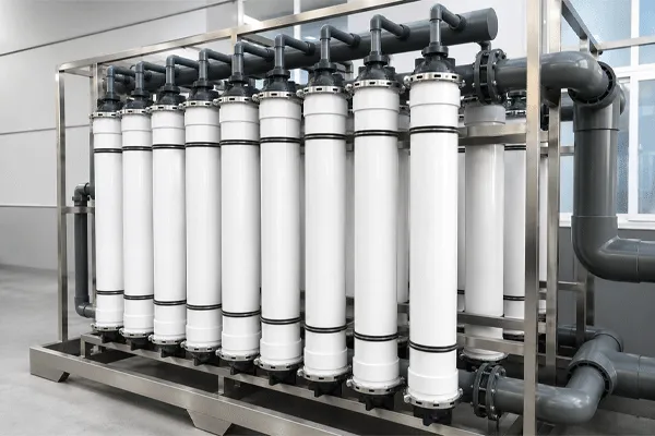
Membrana UF a fibra cava: PVDF vs PES e modalità di flusso
Inside-out or outside-in? The feed solids decide
Flow mode determines where solids accumulate and how they are removed, which in turn determines the prefiltration you have to draw upstream.
| Dimension |
Inside-out (lumen-side feed) |
Outside-in (shell-side feed) |
| Solids tolerance |
Lower; lumen plugging is the failure mode, and a plugged fiber does not recover with normal backwash |
Higher; solids stay in the shell volume where air scour can move them |
| Prefiltration requirement |
Strainer sizing is a hard requirement and must be stated in the P&ID; fiber inner diameter sets the limit |
Coarser screening is normally acceptable; still required for debris that can wedge between fibers |
| Fibrous and stringy matter |
Poor tolerance; fibers and hair bridge at the lumen entrance |
Better tolerance, which is why it dominates in wastewater reuse and in submerged configurations |
| Hydraulic predictability |
Higher; crossflow inside a defined channel is straightforward to model and to verify with pressure drop measurement |
Lower; packing density and flow distribution in the shell create zones that are harder to predict from a datasheet |
| Cleaning mechanics |
Backwash plus forward flush; the flow path is defined |
Backwash plus air scour; the scour rate becomes an operating cost line and an aeration design input |
| Packing density |
Usually lower area per module footprint |
Usually higher area per module footprint |
| Where it fails in service |
Irreversible lumen blockage after an upstream upset |
Uneven fouling across the bundle when scour distribution is poor |
The failure asymmetry matters more than the performance comparison. An inside-out module that suffers a strainer bypass event can lose capacity permanently in a single shift. An outside-in module that is under-scoured loses capacity gradually and usually recovers with a corrected cleaning regime. For a design institute carrying design liability, that difference in failure recoverability is worth more than a small difference in packing density.
Matching material and mode against four feed cases
| Feed case |
Governing constraint |
Flow mode |
Material bias |
What to verify before issuing the spec |
| Municipal surface water ahead of RO, chlorinated raw main |
Sustained oxidant exposure |
Either; inside-out is common where turbidity is controlled |
PVDF-leaning |
Where dechlorination sits relative to the UF; whether the RO train needs its own SBS dosing regardless |
| Groundwater with iron and manganese |
Inorganic scaling and irreversible fouling |
Inside-out acceptable if pretreatment removes precipitate |
Either; the oxidation step matters more than the polymer |
Whether oxidation and filtration precede UF, or the precipitate forms inside the module |
| Secondary effluent for reuse |
Filamentous solids and organic fouling load |
Outside-in |
Either; cleaning regime decides |
Caustic CIP temperature and frequency; scour air rate and its energy cost |
| Industrial process effluent with variable organics |
Fouling reversibility, not average flux |
Outside-in |
Depends on CIP chemistry |
Pilot data on flux recovery after each cleaning cycle, not first-day flux |
Compared with the catalogue-driven approach common among membrane module suppliers, where a model number is matched to a required flow rate and the material follows whatever that product line uses, this sequence starts from feed chemistry and cleaning strategy and lets the module follow. It produces a longer specification and fewer clarification rounds.
The misconception that survives most tender reviews: pore size ratings are not comparable
Pore size and molecular weight cut-off are published for nearly every UF module on the market, and engineers routinely compare them across suppliers as if the numbers shared a definition. They do not.
Nominal pore ratings in UF are typically quoted somewhere between roughly 0.01 and 0.1 µm, but the value depends on the challenge test used to derive it: which particle or macromolecule, at what concentration, at what rejection threshold, and whether the figure is nominal or absolute. A nominal 0.03 µm rating from one manufacturer and a nominal 0.03 µm rating from another can describe measurably different retention curves.
The consequence for a design document is practical. If a specification is written as “pore size ≤ 0.03 µm,” any supplier can meet it on paper. Write the requirement as a retention performance instead: turbidity and SDI at the UF outlet under stated feed conditions, plus an integrity test method and pass criterion. That version is testable at commissioning.
The same reasoning applies to design flux. A flux figure with no temperature reference, no TMP limit, and no fouling allowance is a marketing number. Require flux at reference temperature with the temperature correction basis stated.
Eight fields to require in the UF datasheet request
Send this list with the enquiry rather than accepting a general catalogue sheet. It shortens the evaluation and exposes which suppliers hold real test data.
- Membrane material, including whether hydrophilic modification is a blend or a surface treatment, and whether it is permanent or subject to gradual loss.
- Flow mode and configuration: inside-out or outside-in, pressurized or submerged, and the fiber inner diameter for inside-out modules.
- Nominal rating with the test basis stated: challenge species, concentration, and rejection threshold.
- Design flux at reference temperature, with the temperature correction method and the fouling allowance applied.
- Operating and maximum TMP, plus the backwash pressure limit and the maximum permissible transmembrane reverse pressure.
- Chemical tolerance expressed as cumulative exposure: chlorine ppm-hours, pH range at CIP temperature, and the maximum CIP temperature at module level.
- Module dimensions, effective area, connection sizes, and rack compatibility if this is a replacement.
- CIP protocol: chemicals, sequence, contact time, frequency assumed in the flux figure, and the flux recovery expected after each cleaning.
- Integrity test method and the pass criterion the supplier will accept at commissioning.
- Expected membrane life under the stated regime, and the basis on which it is stated.
Items 6, 8 and 10 are linked. A membrane life figure that is not tied to a specific cleaning regime and a specific chemical exposure cannot be evaluated, and it cannot be enforced later.
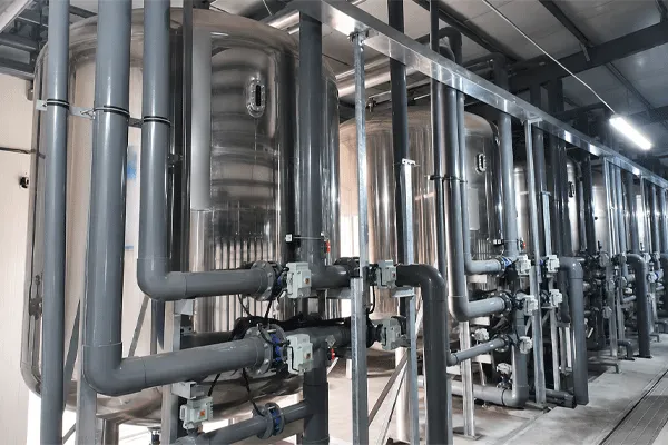
Membrana UF a fibra cava: PVDF vs PES e modalità di flusso
Banott Hollow Fiber UF Membrane: documented scope and the fields to request
The Banott hollow fiber UF membrane series is supplied in multiple membrane materials and flow modes rather than a single fixed configuration, which means the selection logic above applies directly at enquiry stage rather than being constrained by one product line. The published operating positioning is low-pressure filtration for removal of suspended solids, colloids, and microorganisms, used either as a standalone purification stage or as pretreatment ahead of RO. Within Banott’s wider scope the same supplier also covers Membrane RO, Moduli EDI, MBR modules, and containerized plants, so a UF stage specified here can be carried through to the downstream train under one technical interface.
| Published parameter |
Documented value |
| Product family |
Hollow Fiber UF Membrane Series |
| Materiali |
Multiple material options available; specific option list to be confirmed at enquiry |
| Flow modes |
Multiple flow mode options available; inside-out and outside-in variants to be confirmed at enquiry |
| Operating pressure class |
Low-pressure operation |
| Removal targets |
Suspended solids, colloids, microorganisms |
| Typical duty |
Standalone water purification; RO pretreatment |
| Pore size / MWCO, design flux, module models and effective areas |
Not published; request the datasheet |
| Pricing |
Not published; quotation on request |
For a design institute, the practical step is to send feed water analysis and the required UF outlet quality with the enquiry, together with the ten fields listed above. Banott’s stated design approach starts from influent data and the target effluent standard rather than a catalog model number, so the datasheet returned against a defined feed is more useful than a generic series sheet. According to Banott’s own published statement on its water treatment engineering team, the group’s experience in ultrafiltration membrane separation technology and engineering application spans close to two decades; use that engineering contact at the pre-sales stage, which is what it exists for.
Where this comparison stops being useful
Material and flow mode selection narrows the field. It does not settle three things that will decide the plant’s actual performance, and they need separate work.
Fouling reversibility on your specific feed is only established by piloting. A three-week pilot that measures flux recovery after each CIP tells you more than any datasheet comparison, because the number that matters is not first-day flux but the flux the module holds after twenty cleaning cycles.
Aeration and backwash energy on outside-in configurations should be costed into the OPEX model before the module is selected, not after. On reuse duties the scour air can be a larger operating line than the feed pumping.
Finally, the interface with the downstream RO stage sets requirements that UF datasheets rarely address directly: SDI target at the RO inlet, permissible oxidant residual, and how a UF integrity failure is detected before it reaches the RO elements. That interface, rather than the polymer choice, is usually where a UF-RO train underperforms.
FAQ
Q: Is PVDF always the better choice for chlorinated feed water?
A: It is generally the safer default for sustained oxidant exposure, but the deciding evidence is the supplier’s cumulative ppm-hour rating and the definition of end of life behind it, not the polymer name. A well-modified PES module with a documented exposure rating can be appropriate where dosing is intermittent and controlled.
Q: Can I specify inside-out for secondary effluent reuse?
A: It is done, but it moves the risk into prefiltration. You would need fine straining sized against the fiber inner diameter, plus a strategy for what happens when the strainer is bypassed during an upset. Outside-in tolerates fibrous solids without that dependency, which is why it is more common on reuse duties.
Q: How do I compare pore size ratings between two suppliers?
A: You cannot compare the numbers directly unless both state the same test basis. Ask each supplier for the challenge species, concentration, and rejection threshold behind the figure, then compare on outlet performance criteria instead: turbidity, SDI, and the integrity test pass criterion.
Q: Does the flow mode change how the UF stage is drawn upstream?
A: Yes. Inside-out requires a strainer whose aperture is tied to the fiber inner diameter, and the P&ID has to show it. Outside-in normally accepts coarser screening but adds a scour air supply, which appears in the aeration schedule and the electrical load list.
Q: What UF specifications does Banott publish, and what has to be requested?
A: The published series information covers material and flow mode availability, low-pressure operation, and duty positioning as standalone purification or RO pretreatment. Pore size or MWCO, design flux, module models and effective areas, and pricing are not published and are provided against a stated feed water analysis on enquiry.
Q: Should the UF material choice be made before or after the RO stage is sized?
A: Before, in most cases. The UF outlet requirement is set by the RO inlet requirement, so the RO stage defines the target the UF has to hit. But the oxidant handling strategy has to be resolved across both stages together, since the RO membranes need protection from free chlorine regardless of what the UF material tolerates.












 17:20
17:20